
BACKGROUND
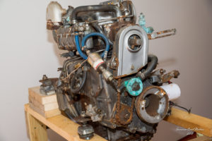
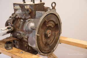
The boat is fitted with a 20 horsepower Yanmar 2-cylinder diesel engine, model 2QM20, coupled to a Kanzaki transmission. These trusty engines are good little workhorses and can be found in numerous applications in addition to offshore power. Although this model has changed over the years, spare parts are available and serviceable units still command a good price.
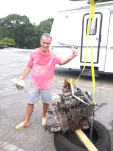
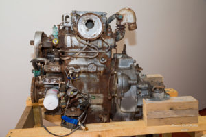
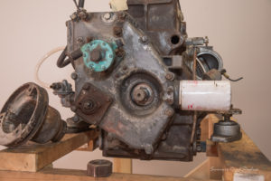
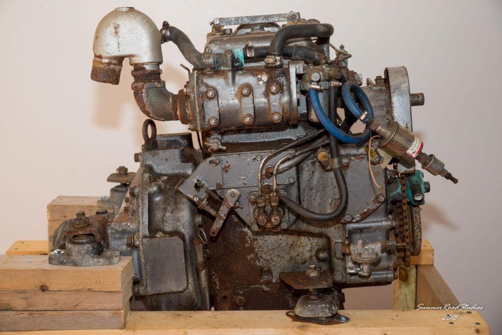
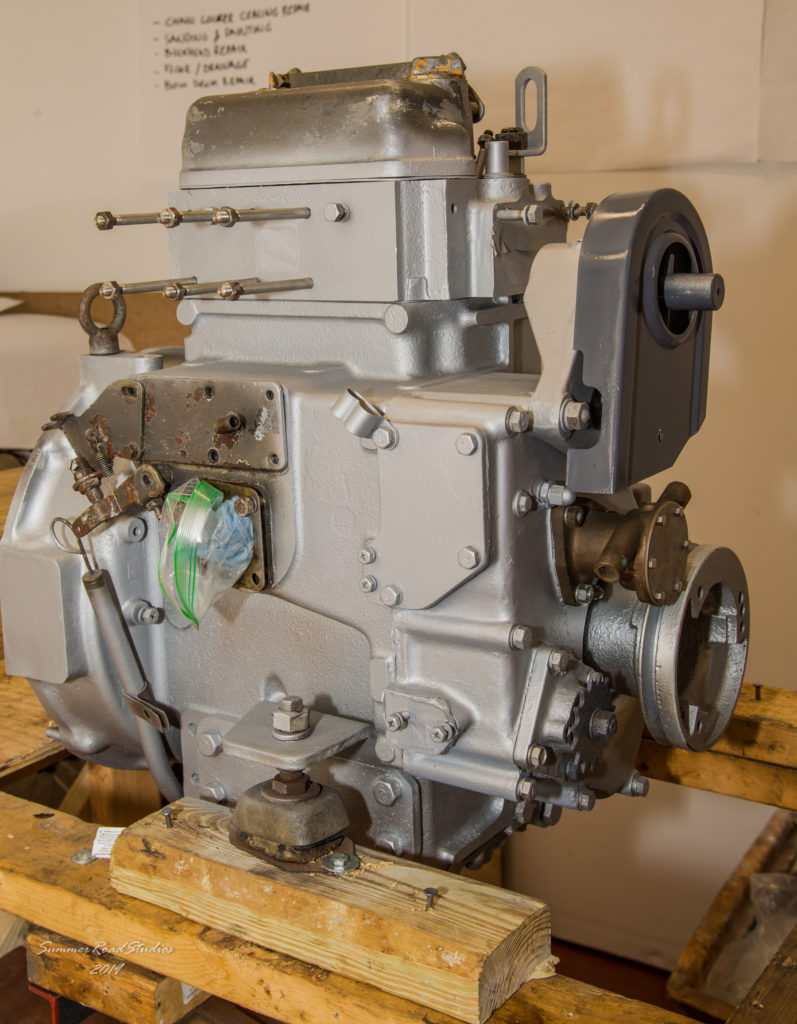
When the boat was purchased, it was stated that the engine had approximately 1500 hours running time but nothing else was known. On first inspection, the engine looked to be in poor condition with evidence of water coolant leaks and severe corrosion on much of the block and ancillary parts. But at least it was intact and had not suffered from some long-ago, half-started repair. There were no signs of oil leaking from the engine or transmission which again was a promising sign. So, the first step was to remove the engine from the boat and get it examined.
More initial thoughts here: http://www.cruisersforum.com/forums/f54/yanmar-2qm20-should-i-rebuild-or-replace-it-maybe-convert-to-electric-203709.html
JULY 2018 – ENGINE REMOVAL
With the boat now firmly on dry land, the removal was done using a portable hydraulic work platform as a crane to lift out the 450lb, (200kg) engine and transmission. As can be seen, the boat is covered by a framed tarp so the lift had to clear that before it could be set down. The plan was to set the hoist as close to the boat as possible but on the day we found a newcomer had parked their boat beside ours so we had to extend our boom using a handy fence post from a nearby landscaping truck. By our extremely rough calculations we had a 450lb load on a 500lb crane, (plus an 6ft extra boom to complicate the math!).
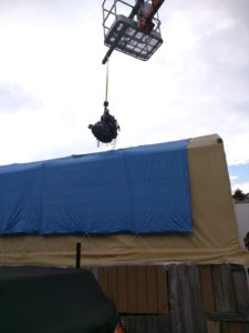
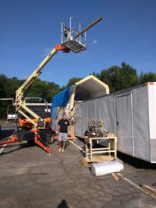

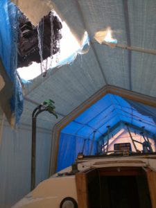
Cautiously, we slowly lifted it up from the engine well, through the companionway, (it cleared by inches) and over the hull to the ground below. At any moment we were expecting something to snap or the platform to collapse and send the whole thing through the deck… Success and one big sigh of relief!
Oh, don’t worry about that big hole in the tarp; the next day we used the platform to put a new, custom made, heavy duty tarp over the frame.
AUGUST 2018 – FIRST IMPRESSIONS
Once secured to an engine stand in Carlos’s garage, the first test was to determine if it would turn over by hand; yes it did. So, it was not seized but that was all we knew. I took the decision to strip the entire engine down, examine what we found and if nothing untoward was seen, reassemble it using new parts where applicable. Thanks to the power of E-Bay, Carlos has found a copy of the original mid-70’s Yanmar service manual so I did not feel entirely alone. Being Japanese, we had to first buy a set of metric sockets and wrenches before proceeding. At every step, I photographed the steps in hi-resolution as a record of what was done and to act as a guide during re-assembly. As parts were removed, they were placed in poly bags or plastic tubs and marked with a description.
Being a marine diesel engine, it weighs a lot more than a similar gasoline motor so our ability to pick it up and take it to specialized machine shops was pretty well nil. We were committing ourselves to doing the overhaul and getting it running again in Carlos’s suburban garage.

SEPTEMBER 2018 – Engine strip down -1
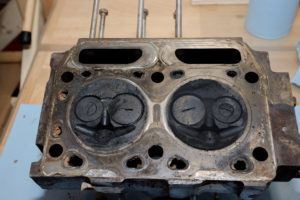
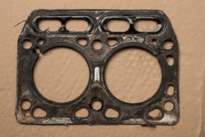
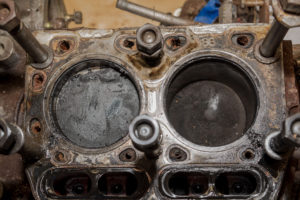
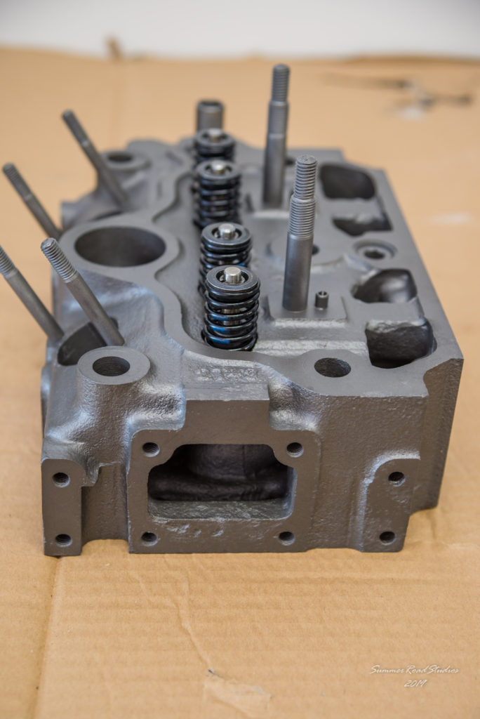
Once the cylinder head was removed it was clear that the head gasket had failed in the past and allowed oil and/or water to contaminate one or both cylinders. Considering the age of the engine, there appeared moderate carbon build-up on the piston crowns and in the combustion chambers. So far, so good.

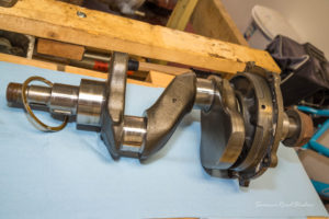
Removing the flywheel and crank took some effort, not just for the non-existent special tool that the handbook instructed me to use, but also for the incredibly stubborn nut on the front pulley. I had to make a flywheel puller tool from steel bar for that end of the crank whilst an industrial impact wrench finally got the 30 mm. pulley nut to move at the other. That nut resisted all sizes of breaker bar and a blowtorch before I went and rented the impact wrench.
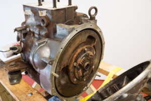
With the crank out the main bearings could be inspected and both showed signs of wear on the lower surface; quite understandable for the vintage. Fortunately, there was no sign of metal detachment, scoring or overheating which was good. So the crank was put to one side and it was agreed that the main bearings should be replaced now that we had got this far. The head, we decided, would be sent out to a local machine shop to be checked, cleaned and have new valves and springs fitted. A relatively simple task perhaps but I’d rather have an expert tell me the heads warped or cracked than find out much later myself.
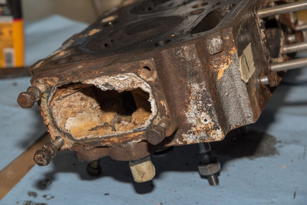
There was a lot of scale build-up in the head and exhaust manifold, which, based on the last few atoms of metal left on the two zinc plugs was really not surprising. I had a slowly dawning suspicion that this poor engine had been starved for cooling water in its last few years and had been overheating. Hence the signs of water leaks around the coolant pump and hoses.
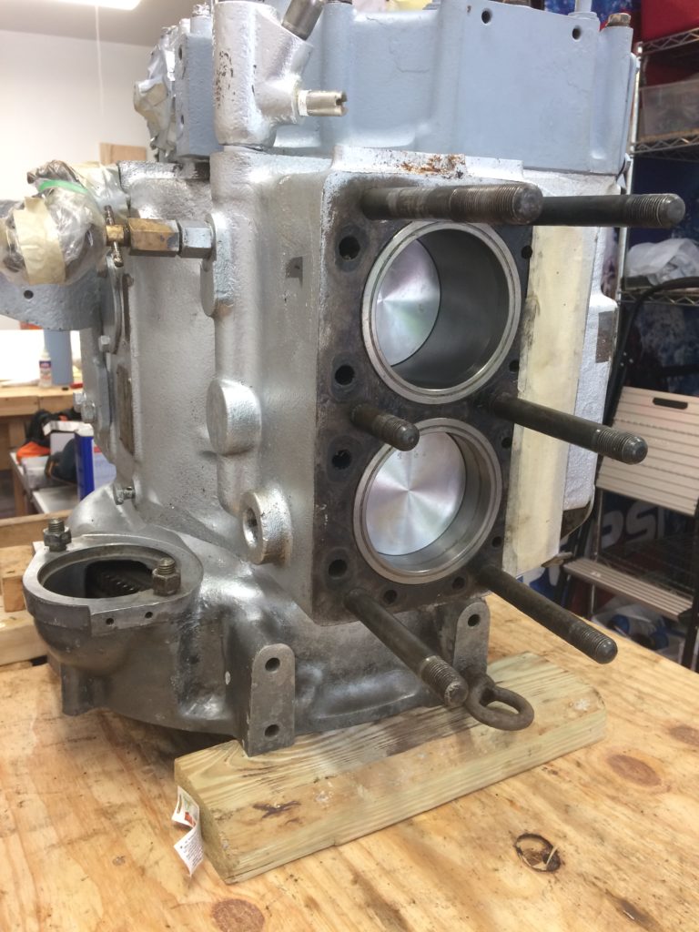
OCTOBER 2018 Engine strip down – 2.
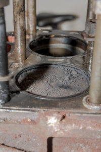
With the pistons out and the crank removed, (after ensuring timing marks were visible), it was time to examine the cylinders. They really did not look that bad and I would have been happy to hone them before adding new rings. Since this engine had wet liners, we decided to replace them as well. Now, if you try and buy a diesel engine liner removal tool you will invariably wind up among the kind of battleship-sized stuff used by people who service things with names like CAT and Kenworth on them. With no chance of finding an original 40-year old Yanmar special service tool I was starting to think this might be a dead end, when I saw an affordable custom puller on E-Bay. Once the advertiser had the bore dimensions from me, he sent back a very well made puller within a week.
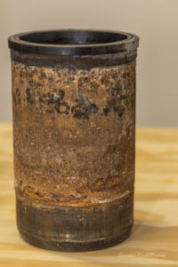
Good grief, these things can be stubborn! According to the trusty Yanmar service manual, the cylinder liners can be easily removed and replaced. Not this one. It took a four foot breaker bar on the liner tool nut and all of my strength to get the liner to move. Once out, it was not hard to see why. The liner surface and the inside of the block were heavily corroded, no doubt a result of the absent zincs. So, how hard is it to put a new liner in? Easy! Once all the scale and carbon has been cleaned out, it slides straight back in. Amazing!
NOVEMBER 2018 – Engine strip down – 3.
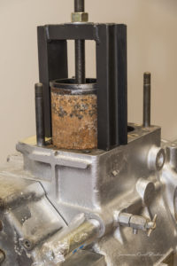
So, now I hit the next problem; removing the main bearings and pressing in new ones. Again, the manual makes reference to a screw press tool that is used for this but any hope of finding one now has long passed. With the block weighing over 200 lbs in its stripped down state, it’s not feasible to take it to an outside shop. I need to have a replacement tool made to the Yanmar design. Working on that now.
February 2019 – Engine strip down; update.
I contacted the person that made the puller tool, gave him dimensions of the bearing plus a copy of the handbook page describing the Yanmar tool and yes; he has made us a die set tool that looks like it will do the job!
March 2019 – Engine strip down; update.
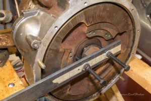
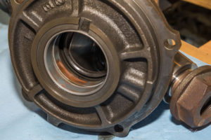
The bearing removal dies have now been received and we have changed the main bearings using the puller tool. It was not easy since considerable force is needed to press them out and in, (as noted in the handbook!) and care must be taken to align the oil passages in the block.
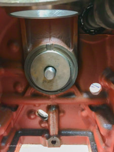
Here’s the view from inside the block as the front bearing is going in.
The puller threaded rod and nut did not like the force being put on them for this task and I have had to replace them, now that the job is done. If anybody needs custom made Yanmar liner removal tool, (with optional main bearing dies), let us know because you can’t buy these anywhere else!
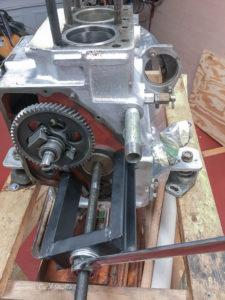
Once the bearings were in I gingerly offered the crank back up to see if we had a really tight fit to cope with. If yes, it would have meant somehow freezing the crank and heating the block in order to get them to go in but no; the crank slid in snugly. Relief all round! Next, I’ll start adding back the timing gear and oil pump before fitting the flywheel. I need to hold the crank solid whilst the flywheel nut is torqued so pistons and con rods will follow after that.
March 2019 – The head gets a new lease on life.
The cylinder head is back from the machine shop with new valves, springs and seals and it looks great! Sandblasted and clean, it is now ready to go back on the block once I have got the pistons and rods in. A local automotive machine shop did the work in less than two days and did not find any issues with the part. So good news there!
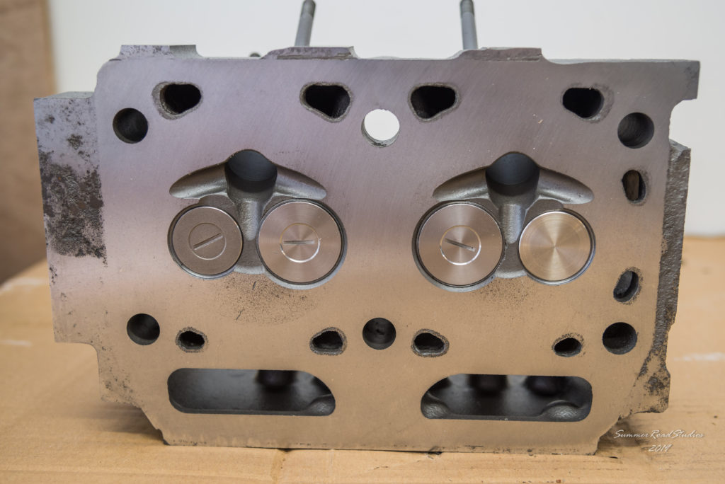

Cylinder head as it was.
May 9, 2019 – Back to the re-build.
This week I took a break from working on the hull fittings and got back to the engine re-build for a few days. Principally to refresh my memory as to where all the parts were and also to get the engine sealed up again before any corrosion sets in. With all the new parts ready and waiting, it was time to get the front crankcase back on, re-attach the flywheel and add new pistons. First thing to do was to re-fit the crankcase gear housing timing cover and re-attach the governor spring and link arm. Quite a lot of delicate feeling was needed before the link arm dropped into place on the injector pump pin. With the timing cover back on and sealed, it was time to tip the block to vertical on its stand so that it would be easier to work on the oil pan when that came to be sealed. No easy task with almost 400 pounds of uncooperative steel.
Now it was time to assemble the new pistons and rings along with new bearings. The original Yanmar handbook was a godsend for this task with its carefully laid out instructions and diagrams.
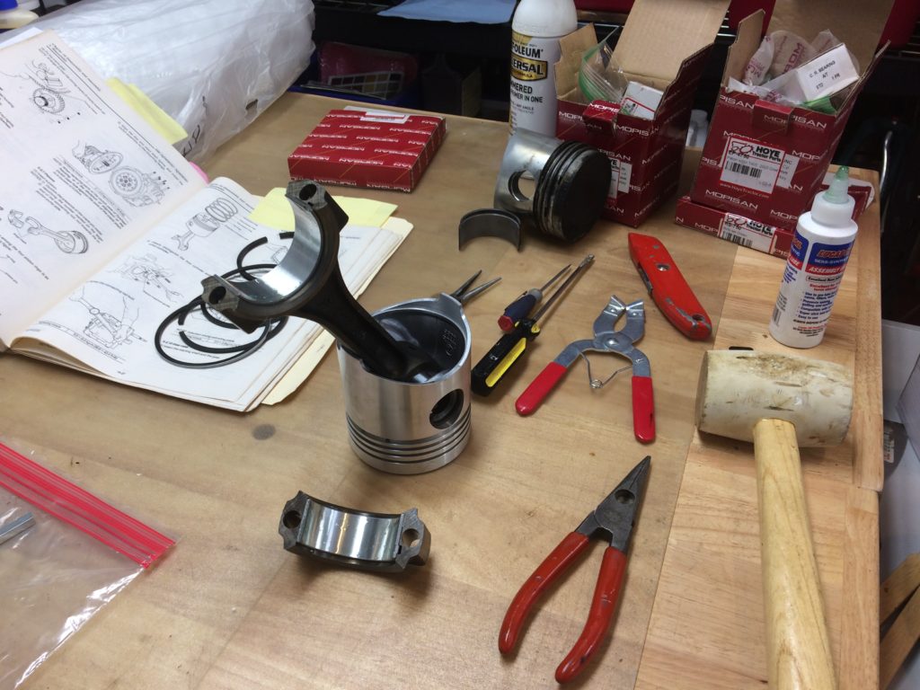
Both pistons slid into the new cylinders with the help of a ring compressor and before long were torqued down on the crankshaft. With the block sitting vertically, it was quite easy to reach both the crank and the piston crown to align them.
Turning to the other face of the block, the oil pan was given a final clean to remove any last trace of old gasket sealant before it was sealed up with new gasket and ThreeBond sealant.
Fresh paint will be added before we’re all done.
Next up; turn the block back to horizontal on the stand so that the cylinder head can be put back with all the associated top end valve gear. After that, all the ancillary parts can be added from our carefully labeled and stored collection.
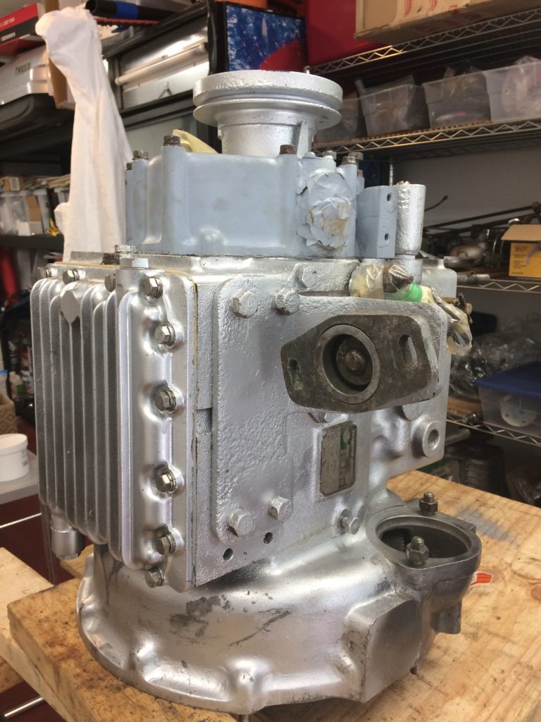
Status Update – May 2019.
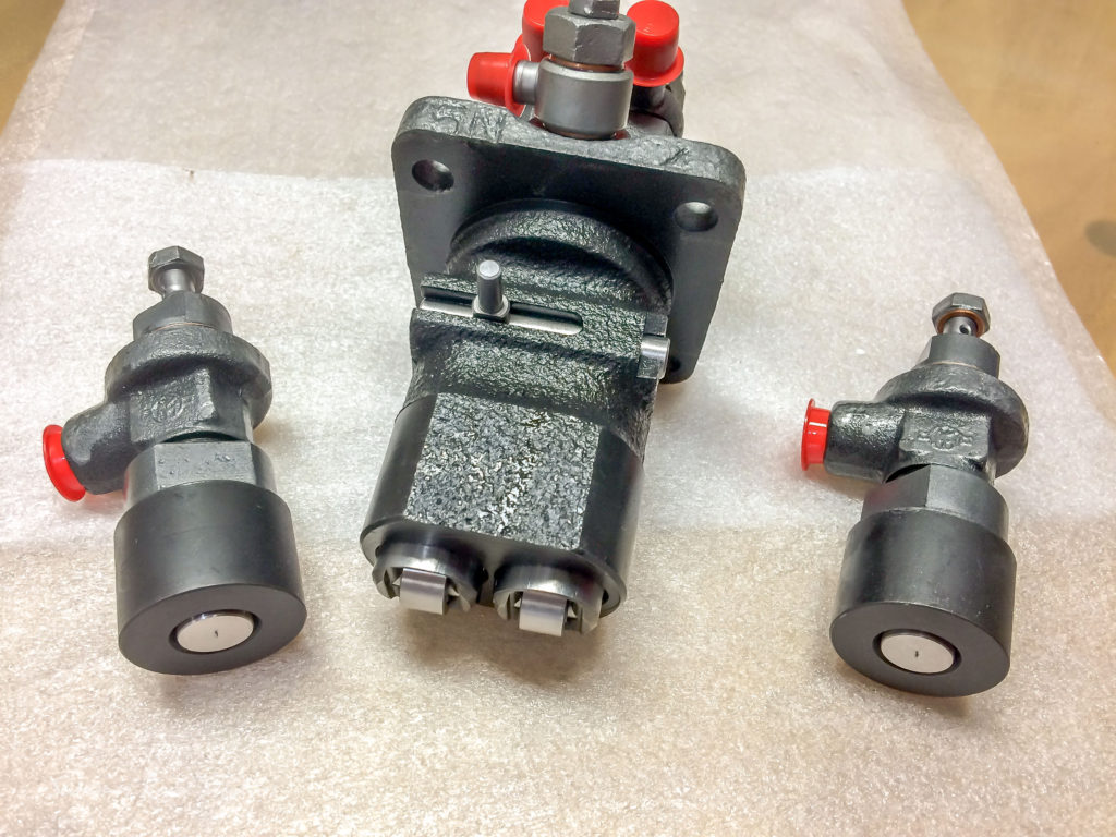
Here’s the current situation with the Yanmar rebuild. The engine has new liners, pistons, piston rings, main bearings, thrust bearings and big end bearings all fitted. The head has been fitted with new valves and springs after being cleaned and machined. A new water pump was found in the collection of miscellaneous spares that came with the boat and now graces the engine gear case cover. It’s all now back together with fresh paint applied. The injectors and injector pump has been sent away to Florida to be serviced, something that should only be done after many hours of running.
Overall, all that remains is for the valve tappets to be set, the injectors replaced and the pump timing to be adjusted. Then come all the ancillary parts; exhaust manifold, water hoses, exhaust system, fuel pump, fuel filter, fuel lines, alternator, hand crank chain and the lube system pipework. I’ll be taking a break from this for the summer as I’m heading off the the UK for a long driving tour of the scenic byways.
See you in September! DJ
December 2019 update.
Well its been a while but I have at last been able to get back to the engine rebuild. With the cooler weather moving in putting a delay in fiberglass work, I was keen to get the engine completed before I forgot where I left off. Anyway, the injectors and injector pump are now back in place after they were serviced by Everglades Diesels in Fort Lauderdale, Florida. They look great! I put the pump back with the original shim set and I’m hoping that the cam timing will still be good. The valve clearances have been re-set to compensate for the head work and new gasket.
Next come the fuel lines, new oil and coolant senders, hoses, fuel pump and filter unit. When replacing the exhaust manifold I looked at the drain valve and sure enough it was blocked solid with old carbon and corrosion. All of the exhaust system was heavily corroded after years of hot gases and saltwater being blown through it. After breaking open the mixing elbow fittings I found that the cooling water feed connection fitting was yes, blocked solid.
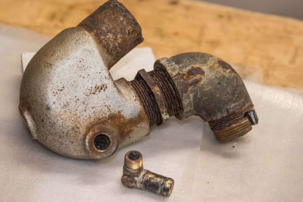
So it was not surprising that the engine had suffered from overheating, leaking coolant hoses and poor performance if you take all these together. The zincs were long gone, the thermostat blocked shut, the manifold corroded, the mixing elbow partly blocked, the cylinder jackets badly corroded… the list goes on. We plan on replacing the mixing elbow with a new stainless steel assembly to reduce this corrosion issue going forward.
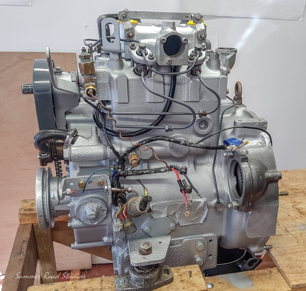
The engine wiring harness has been cleaned up this week and some connectors that were broken or corroded changed. The original alternator looks to be in pretty bad shape so this will be changed for a new one, perhaps of a higher rating. The original unit is most probably a 30 amp Japanese auto model and we may bump this up to 70 amps. We have discussed increasing the alternator rating to cope with higher future battery loads so this should be a worthwhile move. Any move to add a substantially bigger alternator must take into account the existing wiring and the extra load on the engine plus additional heat given off. We’ll get to this later as we start to plan the electrical loads and services.
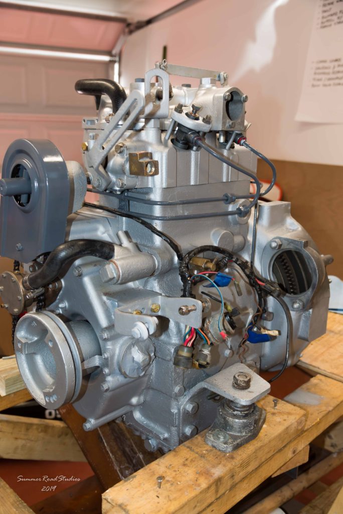
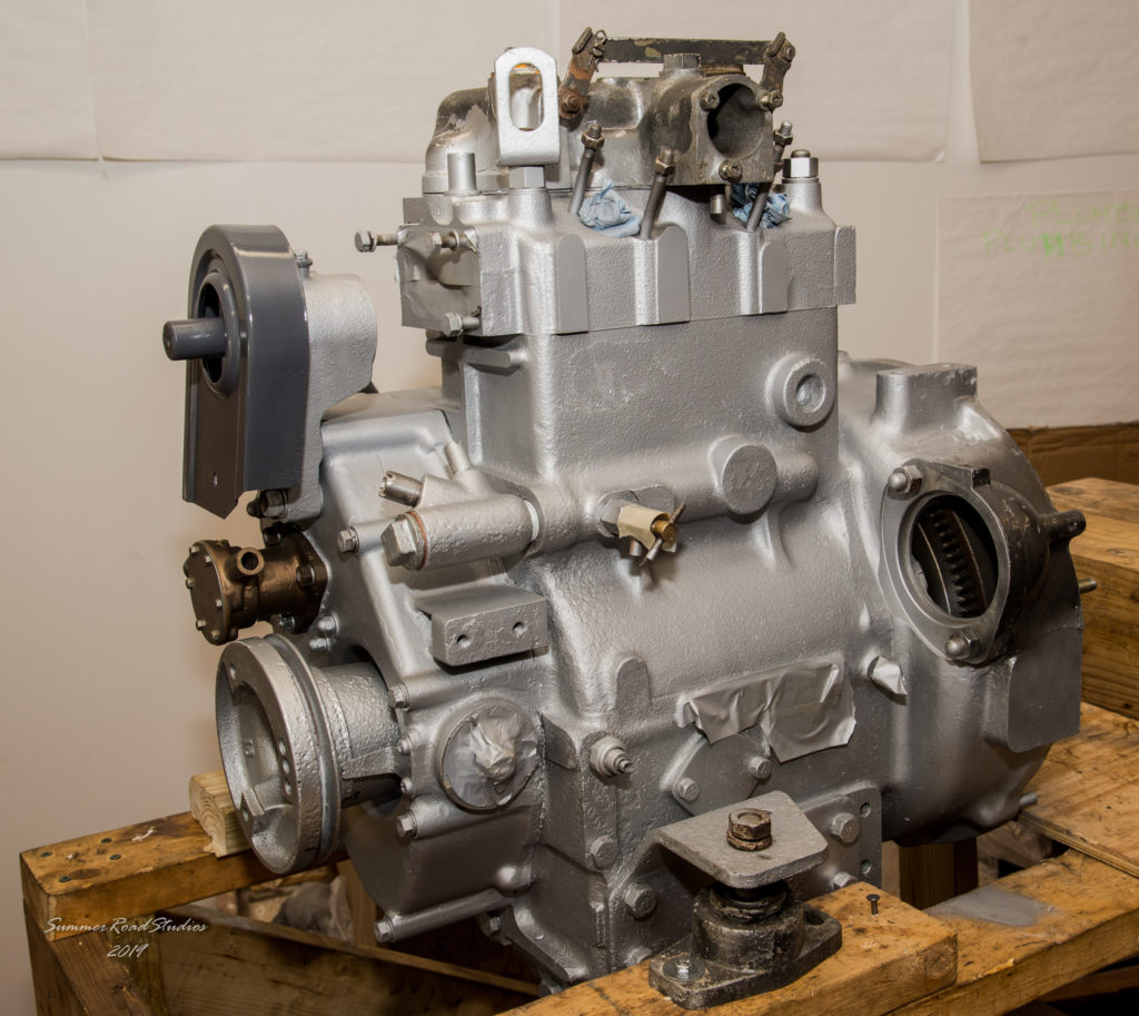
As you can see from the pictures, the fuel lines have not been connected yet since they will need to be open to bleed the fuel system prior to starting. The starter motor has been cleaned and the brushes inspected so this will probably go back. If there is any sign that it’s not engaging or not working, the unit can be swapped easily.
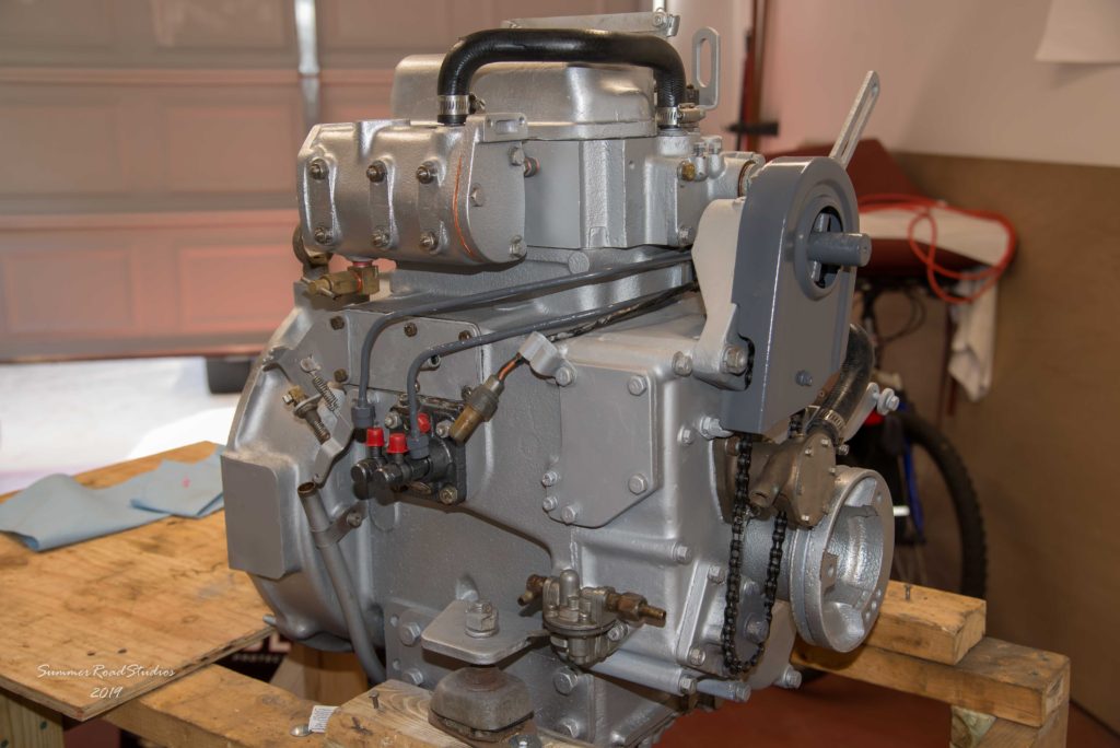
So, as you can see from the pictures, that sad looking rusty lump now looks quite spiffy with all its new parts and fresh paint. It may not be Yanmar gray but its heat resisting and bright; so there. We still have a few more pieces to add; the exhaust mixing elbow, alternator, starter, fuel line and new senders for oil and water gauges. It came with an electric fuel pump which I presume a previous owner added to avoid the chore of bleeding the fuel system before starting. It appears that the mechanical pump works so we’ll decide soon if we keep the electric unit in place.
Currently, all of the high pressure fuel lines are not connected but left undone ready for initial fuel feed bleeding. Before any attempt is made to start it, we will fit a mechanical oil pressure gauge, add the oil and spin the engine over without compression to check that it has and holds oil pressure. After that, fuel lines will be bled, cooling water connected and it’s time to see if it runs!
One thing we will do before first running is to move it to a new mounting frame that is lower and wider so that the unit will have greater stability. It would be a shame if it spluttered to life briefly before falling over..
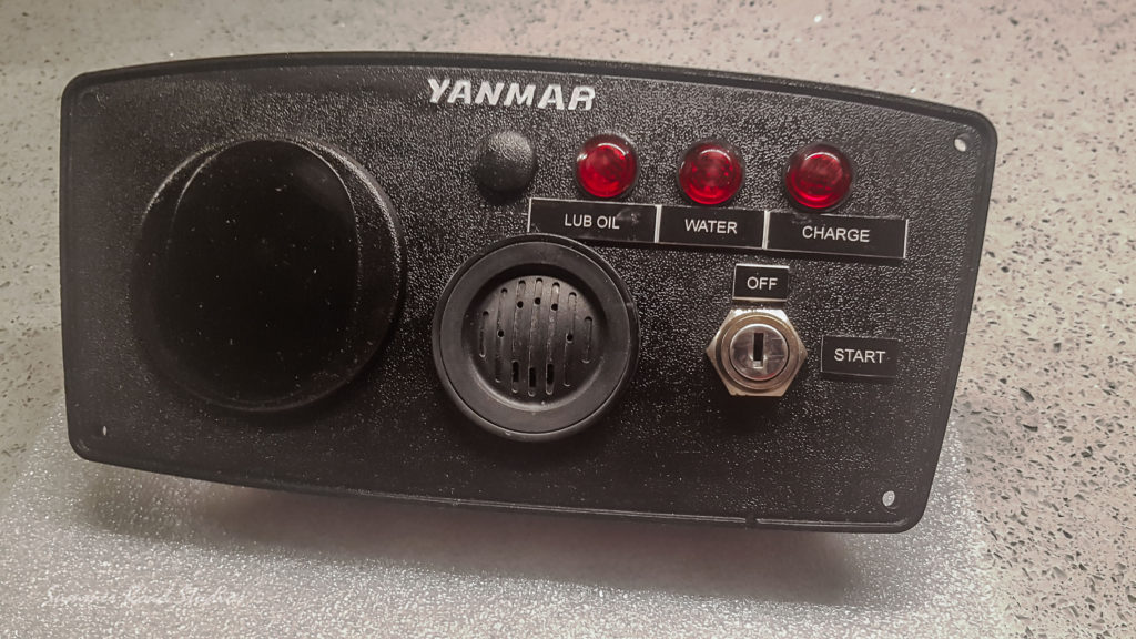
As part of this refurbishment, the engine control panel and cable harness has been freshened up. The cable set has been cleaned of its years of dirt and grime, whilst the control panel has been dismantled, cleaned and repainted to remove the unsightly marks that were on it. I spent a bit of time trying to decide how best to replace the worn lettering on the panel. With such small letters in an almost invisible indent, I did not fancy my chances of successfully painting them in using a tiny brush. In the end I opted to add engraved nameplates.
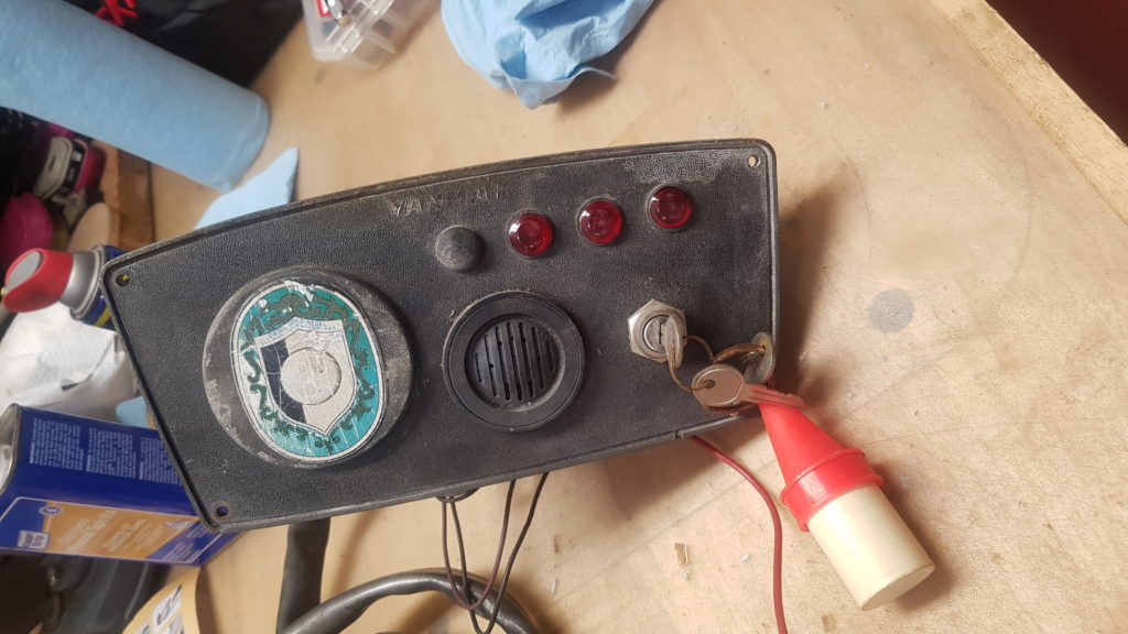
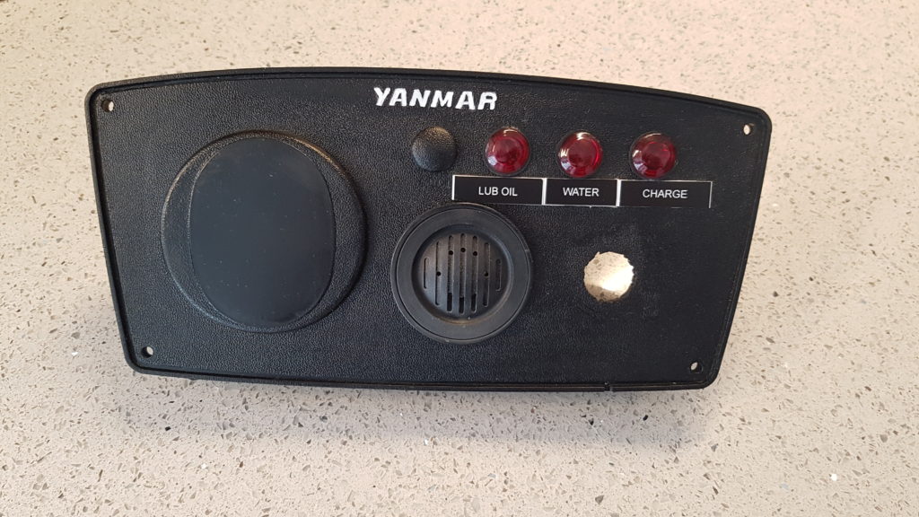
Now all it needs is the ignition switch replacing and perhaps later, a tachometer for the blank space on the left side.
March 2020 – Covid-19 Update.
As you can appreciate, both Carlos and I are now confined inside our own homes to minimize the risk of catching the Coronavirus. This has meant that all progress on the boat has stopped until we can get back outside and suppliers re-open. Carlos is teleworking from home whilst I had to return from New Zealand early to avoid the shutdown. We’ll be back at it soon!
September 2020 – A question of timing..
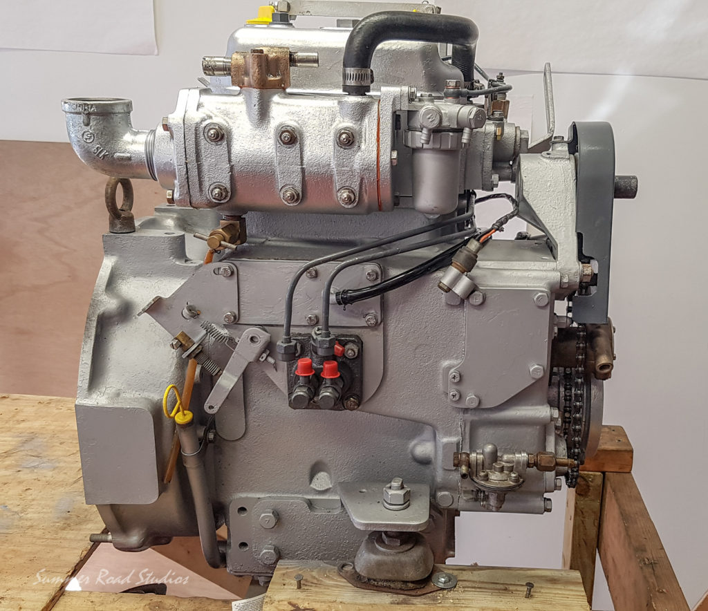
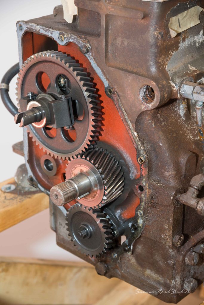
We had a question from a reader regarding timing marks for the injector pump and I realized that I had not covered this issue in any detail. So, here’s my input. As you can see from the picture of the injector pump above, it operates by having those two little rollers on the end press against the camshaft, which is itself gear driven from the crankshaft. As the crank rotates, it turns the camshaft and when one of the cam lobes presses against the injector roller, it pumps a tiny amount of diesel fuel to the injector. At the factory, this gear relationship is set and marks are put onto the gear teeth so that they can be removed and replaced without losing this setting.
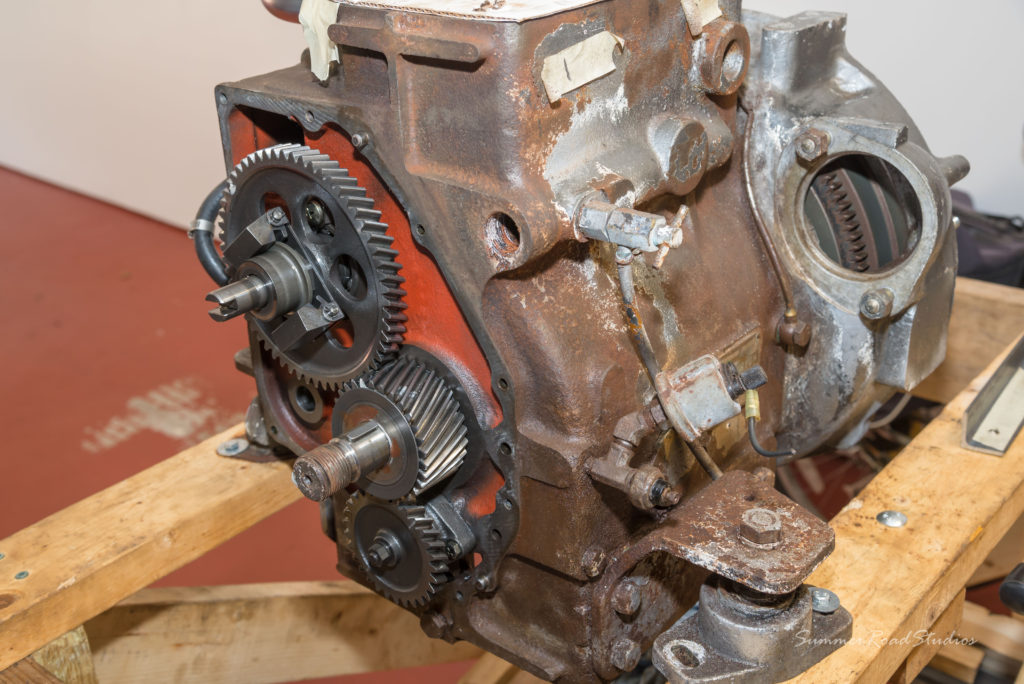
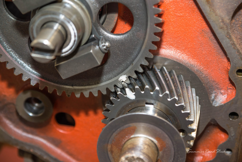
You can see a small 0 stamped on the camshaft gear and a paint mark on both to show where they match. On our engine, I added a clear paint mark before the crank was removed so that it would be easy to see during re-assembly. This sets the basic timing point for the injectors and fine adjustment is made by use of shims between the pump and the block. Adding shims has the effect of moving the pump out and thus delaying the injection point; removing shims moves advances the injection point since the pump rollers are closer to the cam lobes.
July 2021 – A look at the governor system…
A reader is having trouble with the re-assebly of his engine, specifically the control linkage and parts underneath the front timing cover. Since this cover and its attached governor linkage is so difficult to remove, I thought I would try and help by pulling out my pictures from the rebuild to see if it would help. As I said, the removal of this cover is not to be taken lightly since it connects to the injector pump rack and is very tricky to re-attach.
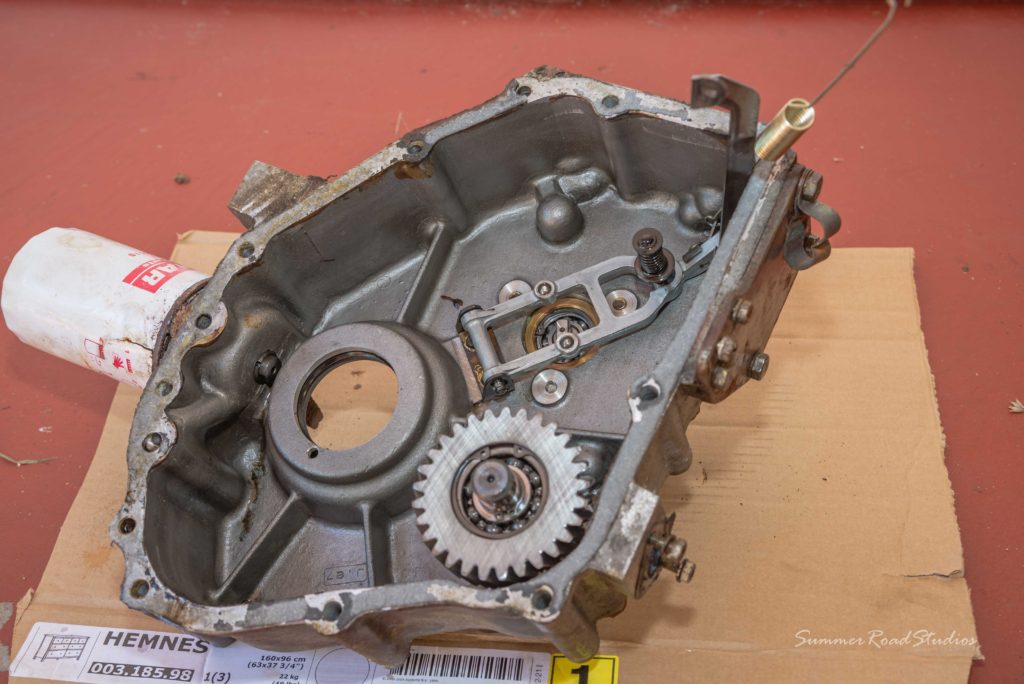
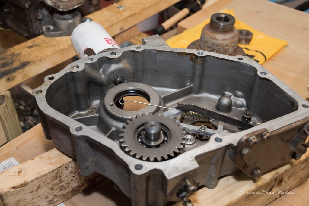
Two springs are shown in the timing cover; one is captive on a shaft that is threaded into the cover, the other is the fuel rack tensioner that maintains slight pressure on arm as it follows the governor weights as they move in and out. If this long spring loses tension over time it will cause the idle speed to fluctuate and make it harder for the throttle to hold position.
Looking good!
Yes it looks like you are doing a great job. It will be like a new motor, except better as they don’t build diesels like the 2qm20 any more. It’s a bit late for you but the 2qm20 is based on a tractor motor & you can buy parts cheaper from tractor dealers. Not sure what the tractor engine model is but Wotname on CF knows. PM him he’s a good guy.
cheers Compass 790
Thank you for documenting your progress so well! I’ve got a 40 year old 2QM20 that will likely need the same treatment within a few years…if kids, wife, funds and time let me! It would be nice to have an engine that I know better as well as can trust for the next 40 years in my boat.
Thanks Paul! We have been ordering some parts from https://www.hoyetractor.com/ and yes, prices are usually cheaper than prices at marine stores. However, they dont have all the parts we needed so we had to order parts from TOAD and other yanmar marine distributors.
Do it!! and let us know if you have questions or need any help
This is an excellent post – thanks so much. Going to be refurbing mine soon!
Wow! I’m jealous. 🙂 Looking fwd to seeing it run
TY! Very informative!
Still have the Yanmar liner removal tool, (with optional main bearing dies) – Still got em? Id take em! Also, where did you find your parts for the rebuild? May do this soon..
Hi! Yes, we already have the tool. We bought the parts at TOAD and HOYE TRACTOR
I need a injection pulling tool please my email address is joffawthen@gmail.com
Hello good morning, I have a 2Qm20 engine with the engine head broken. Do you have a head for sale? or if someone wants to buy my engine? thank you
Hello Carlos and David , just seeing your site for the first time after hearing about you from our buddy Chris.
Wow! You guys are in it deep but it looks like your doing it right.
We are the previous owners of the s/v Spanish Stroll and which had the sit down nav station and qtr berth. I’ll send pictures as soon as I can find them.
I was just checking out your motor job. We had the 2qm 15 What great little motors. Our only issue was heating up every couple of years. We’d pull the little cover off the end of the head and snake it out with a piece of wire. Good for another 2 or three years! It was good having a temp gauge so we could see it coming on. One suggestion, If the motors still out you might want to install a short hydraulic hose into the bottom of the pan. We were able to take the cap off the hose end and drain the oil right into a 2qt soda bottle. What a luxury!
We’ll I won’t get crazy here I tend to go on and on about these boats
Jim
Hi Jim and thanks for reading our little blog. Yes,it appears we are in deep but are determined to bring this boat back to life! The engine rebuild was put on hold this summer whilst we concentrated on hull repairs and bulkhead investigations. I’m actually back doing some more engine building this week while Carlos is in Spain with his family. It does sound like your engine overheating issue could be the result of restricted passages scaling up every few years and your solution seems to work. I do like the idea of an oil drain system to alleviate the contortions required at the moment. The only other solution is to make up a suction pump and suck the oil out via the dipstick. Watch this space! With the motor out of the boat and on a stand in the garage, we have time to figure this stuff out before it has to go back.
Best for now, David
Hello Miguel, I am sorry to hear about your head issue and unfortunately we do not have a spare head for sale. Let us know where are you located and perhaps we can find someone that can help.
Regards, David
Excellent goods from you, man. I’ve have in mind your stuff previous to and you are
just extremely fantastic. I actually like what you have got here,
certainly like what you’re stating and the way during which you
are saying it. You are making it entertaining and you still take
care of to keep it sensible. I can not wait to learn much more from you.
That is really a tremendous web site.
I have a 2T90 tractor engine that I want to replace the main bearings. Do you have the specs on the puller/installer you had made.
Hi Gary, thanks for finding us. Is your engine a Yanmar like ours or another make /model? If it’s a 2QM20 I can give you dimensions of the puck we had made or the name of the machine shop that made them. I sent one of the old bearings to the machine shop and they quoted me a price to make it.
Best regards, David
Hello
I am from Poland and I am also renovating a similar 2T90 engine.
Muj engine is not marine but the block is identical.
You may have documentation for this engine.
Mainly needs tightening torques and valve clearances.
Please help
Hello Marcin and thanks for reading our blog. Here’s some data on the cylinder head that should you. The head bolts should be tightened in sequence, starting from the center and working out to the edges diagonally. Initial torque setting is 6kg/mtr, then repeat at 12 kg/mtr before final tightening at 18kg/mtr. Valve clearance is 0.15mm for both inlet and exhaust, measured at Top Dead Center. Hope this helps and keep checking our site for news of more progress throughout this year.
Best regards, David
hi there, im in Australia and doing a rebuild on my 2qm20, wondering if you still have bearing removal tool and any other special tools that go with it. thanks. jhal5150@ gmail.com
Also would you happen to have all the torque specs.
Excellent work and educational. You might try to find a combination multi-function gauge to fit the space on the panel. Tach, temp, amps, fuel level, and maybe oil pressure. These tend to be 5″ for the bezel OD though. Teleflex and VDO did make these. I believe the Yanmar plumbing is all done with BSP threads and harder to find matching senders. You could consider adapting to FWC or just a regimen of switching to a fresh water feed line at final shutdown.
Hi Miguel – Have a 2qM20 head that I have removed the valves and springs. It is used but doesn’t appear to be cracked. Ill have to take it out and check it for flatness. Interested let me know. Jon
Hi James and thanks for reading our blog.
My best suggestion for the bearing removal tool and/or liner removal tool is to contact a friendly machine shop and ask them to make a stepped steel drift that you can use to drive the press fit bearing. I can give you dimensions from the piece made for us. The same kind of stepped puck can be used for liner removal and you should be able to get a puller frame fabricated as shown in our pictures. Those bearings are very hard to extract and replace so a fine thread high tensile bolt is best. Applying local heat may also help. Torque details are shown below in a previous reply. Best regards, David
Thanks for reading our little blog,
The boat already has a seperate instrument panel in the cockpit that has oil pressure and coolant temperature gauges and these will be renewed later in the process. The blank on the original Yanmar panel will either be used for a new running hours meter or a tacho. (or a single combination gauge). Adding a tacho will require an upgraded alternator which is also planned for the future. Best regards, David
Top work guys. Wish my old 2QM20 looked like that! Hopefully once this virus madness is over and funds can be replenished, I can give it some time and attention! Good luck and fair winds!
Regards
Pip
Hi Pip and thanks for the compliment! We have a lot of work ahead of us and this virus madness is not helping at all. Anyway, keep checking back because as soon as we can both get back to work on the boat, the sooner it can be back under sail. Best regards, David
Hi David, I have a 2QM20 in my yacht here in NSW, Australia. Over the past2 years I have fitted a overhauled head and fuel injector pump and a newish exhaust manifold. All while still in the boat. I envy your space on removal!!
A question. In the picture of the completion of assembly, exhaust manifold side, there is what appears some sort of sensor held in place by a bracket just under the fuel filter. What is it for? I do not have this?
Well done with the rebuild – when do I send mine over??
Cheers
Michael
Hi Michael, Thanks for finding our little blog and a big shout out to NSW! Anyway, that sensor is in fact the harness connector to a tachometer assembly. Like you, our engine did not come with this upgrade and if it did, it would be fitted into the engine in place of that odd shaped plate below the connector. The tacho module is a gear drive module with a shaft encoder that engages with the camshaft gear inside the front gear housing. As you can imagine, finding one of these units is now next to impossible although I did find one on E-Bay some months ago but the owner wanted a fortune for it. Our plan now is to take off a tacho output signal from a new alternator and use that. As you say, having the luxury of being able to pull the engine and rebuild it indoors is a great bonus. Once we’re done with ours, send yours over…
At the moment I am back at the boatshed, about to start the fabrication of the new water tanks for the forward cabin. Due to their size, these have to go back in place before we can fit new main bulkheads. Carlos is still at home on lockdown but managing to get some prep work done on the other tank in his garage.
Best regards, David,
Great information, very helpful. I’m too rebuilding a Yan mar 2QM20, but I have no information regarding the
gearbox assembly. I believe is a Kanzaki gearbox. Do you have any links for parts or any information for parts.
Your response will be appreciated…
Carlos, Grant,Florida
Hi! it’s a KBW10 transmission.I have a spare part catalog. I will email it to you to the email address you entered when you posted your comment. Thanks for visiting our blog!!
Hi David,
Greetings from Oz 🙂
Thanks for sharing your journey. Could you please send the dimensions of your custom pullers that you made?
I am about to undertake the same on a 1979 NorWest 33 in Brisbane.
Take care
Paul
Hi Paul,
Many thanks for finding us and your interest in our rebuild. Here’s the basic dimensions of the liner puller that we used; all in imperial values since it was made locally. I have had to be approximate with some of the values since the unit is not to hand but secure in Carlos’s garage. Anyway;
Puller tool dimensions:
Threaded rod: ¾” x 16 thread, High Strength Steel. Length approx.. 24”
Puller Puck: 88mm bore / 97 mm Overall Puck Thickness: Approx. 1.25” / 32mm
Frame: Approx. 1.5”x 1” steel channel sections, welded corners.
Distance between frame legs: Approx. 6”
For use on the main bearings, we sent one of the bearings to the maker and he made a puck to suit. If you need exact sizes I will have to head over to the garage later and measure it. This should be sufficient for a local workshop to make something up. Good luck and keep us posted of your progress,
Cheers,
David J
This is great. Thank you for sharing this. You’ve done impressive work. I’d love to rebuild my engine.
HI David,
Well done for your work and thank you for sharing all those information. We have the same engine and we are finishing the refit. We have a little question.
On the crank of the injection pump we have a mark (a dot) that we have to adjust to another mark (that we cannot find).
Would you have some information about that ?
I don”t speak very good english but I can send a picture if you don’t understand what we are talking about
Hello and thanks for finding our little blog. I think you mean the timing marks on the crank and camshaft gears which set the injector pump operation point. Both these gears are located under the timing cover on the front of the engine block. I cant think of what other dot marks you could be referring to. I have pictures taken during the assembly that show these marks if it would help but if you want to send a picture of your question, that would be helpful.
Best regards, David
PS: I just added a section on the timing gears with pictures; hope this helps.
After further correspondence, it looks like you have solved your slow idle issue by changing the spring that links the governor to the injector pump. You said the engine ran well on higher throttle settings but was unsteady at the idle setting and we suspected the spring link was stretched. This turned out to be the case. That spring is difficult to remove and could easily get stretched in the process so well done for solving it!
Best regards, David
Hello,
I have just purchased a used 2QM20 and i would like to know which Yanmar tractor equivalent was used for ordering parts. I would like to order a rebuild kit and a few other parts and I can’t find a single part online using 2QM20. One writer mentioned 2t90. Is that it?
Thanks
Larry
I dont quite remember. I would reach out to the guys with https://www.hoyetractor.com, they will tell you for sure.
Thanks!
Carlos
Good web site you’ve got here.. It’s hard to find high-quality writing
like yours these days. I honestly appreciate individuals like you!
Take care!!
Any one selling yanmar 2qm20 second hand engine
I am not selling the engine yet, but I may sell it if the boat doesn’t sell
Hi. I’m refurbishing my 2QM20 too.
I didn’t intend to open the timing cover but I discovered a couple of spring retaining washers in the sump which I traced to a bent fuel injection control shaft. Investigation revealed one of the governor weights was not engaged with the sleeve!! The latter must have smashed into the control shaft. So I must access and fix it.
This brings be to the front crank pulley nut removal. I don’t want to break something for want of understanding.
Can you confirm that the thread is right hand?
Hi Russell, Thanks for finding our blog.
Yes, the crank pulley nut is a conventional right hand thread, metric of course. Ours was really tight to remove and took an impact driver to finally move it.
Best regards, David
i have one in good running condition. where are you located?
Hi again David. I followed your lead and had the crank nut removed by a local engineering shop. I found the injection control spring in the bottom of the timing case and have manufactured replacement injection control shaft and spring retainers. Reassembly is underway.
As I refer to the manual I discover some anomalies: my injection control spring is nearly 50mm long compared with the 24.7mm specified. What’s going on??
Knowing that I must adjust this injection limiter control spring, I will have to ensure all the governor linkages are as specified, as well.
But then I see that the regulator spring is supposed to be 244mm overall length (mine is 185mm !!?). The spring coil part is 40mm, as specified. I wonder if a 244mm spring could even fit between regulator and governor levers?
Sorry to bother you with such details but I’m hoping you would be willing to shed light on these discrepancies.
Can you recall or estimate the spring lengths in your 2QM20?
Another thing: I see the crank and cam gears in yours ate helical cut. Mine are square cut. Curious to see such differences in the same engine model.
And my manual illustrates the governor sleeve with the small face/flange toward the centrifugal weights, and the larger face/flange toward the governor lever. That is not the orientation in my motor. I suspect the manual is incorrect here.
Did you find any discrepancies between the manual and your engine?
Your blog has been a constant reference for me. I really appreciate your effort in publishing it.
Rgb
Hi Larry,
I had to get a replacement 2QM20 head and it turns out that numerous tractor engines of various sizes used the identical head, eg: YM1700, YM2000, YM2200
I purchased from HoyeTractor
Rgb
Hi Russell, Those are interesting points and I have to admit that the engine is now buttoned up and its over a year since I worked on it but I’ll try and work it through. First; good that you mamaged to emove that stubborn crank nut and get access to the timing gears and governor. The injection spring that you mention finding in the timing case; is that the one that holds the governor face against the bob weights? If so, I can’t remember its dimensions on our motor. Or is it the short captive spring that keeps the governor arm under tension? If so, ours looks to be about 25mm with an end cap keeping it in place.
The other dimensional issues are a mystery. Understandably, the regulator spring (or idle spring), must be within a length tolerance or else idle performance will be unstable. Unfortunatly, this linkage can only be connected to the injector rack when the timing cover is in place and its easy to stretch it whilst re-fitting. The result being that an issue will only be apparent when its running again. I’m curious to know where your stated dimensions are sourced from. Helical vs. Square cut gears; I can’t say why yours are diffent. With regards to the governor sleeve; I did not dismantle ours but from my pictures taken, the large flange is against the weights. The manual is generally pretty good and perhaps some illustrations could be a little ambiguious.
Anyway, sorry I can’t be more specific but a lot has happened since I was working on our motor (not least Covid and Carlos’s triplets!).
Good luck and keep me posted. DJ,
G’day again David. Thanks so much for your reply. The spring I found in the timing case is the shorter captive one, on the adjustment shaft that’s threaded into the timing gear case. The centrifugal weights barely miss it as they rotate and the fact that only one weight had been engaged with the governor sleeve meant that the loose one was able to smash the spring and retainers and bend the adjustment shaft. I’ve turned up a replacement.
But now I’m concerned about the spring length. Mine is closer to 40 or 50mm than it is to the 24.7mm specified in the service manual. And yours is as per the manual.
The adjustment shaft is an 8mm diameter steel shaft, threaded ~30mm along one end which is adjacent to a 14mm unthreaded section which then forms a shoulder followed by a 34mm section of 5mm diameter. The spring and retainers fit on the 5mm section and are captive between the 8mm shoulder and the circlip at the shaft end.
What is puzzling is that the manual shows the captive spring taking up the full length of the 5mm section. But that is more than the 24.7mm spring length!
The manual states that maximum diesel injection occurs at the point where the governor just touches the captive spring. To reconcile the spring specs with the shaft dimensions, it suggests to me that there should be room on the 5mm shaft section for the spring and retainers to slide.
I think I’d better get the specified spring length.
I’m reassured that the larger sleeve flange on both our motors are similarly oriented but it reinforces my assessment that there are mistakes in the service manual. (A challenge for amateurs like me who expect the manual to be the last word in these matters!)
You will have a busy life, like most of us, and so I sure do appreciate you taking time to tell me what you know. I take confidence and encouragement from it.
Hi Russ, Your captive spring issue is a real mystery and I wonder how it came to be that one weight was able to be free to damage the post. Your dimensions seems at odds with both your handbook and your eyes so soemthing has to change. Its quite possible that the manual has an original error. So, it makes sense to get a shorter spring, reassemble it in the timing cover and see if it looks better with your own eyballs. I have added a bit more detail to this area on the blog post and I hope it helps. Apparently we’re half a world away so I can only hope that trial and error wins through. The governor control mechanism can only be tested once the timing cover is re-sealed and all the linkages re-attached, hence its important to get it right first time. Let me know how things go. DJ,
David, I cannot recall if I already updated you on the governor adjustment. The service manual instructions are a bit ambiguous but I think i made sense of them.
Even with the longer spring I was able to bring the governor into adjustment according to the specifications. The remaining adjustment is the maximum no-load set screw. I’ll run engine before installation in boat.
I am converting to freshwater cooling to prevent another cracked head. It is a challenge to mount an after market water pump between manual crank starter and the alternator but if you are interested I will keep you posted.
Rgb
Hi Russ, Good to know that you seem to have got the governor adjustment about right so finger crossed going forward. The freshwater cooling mod will overcome a lot of the corrosion isues as well as prooviding a useful on-board heat source. Did you pick-up a used Yanmar manifold for this or is it a third party package? We did look at this option a while ago but the cost seemed high and the documentation on a local convsersion kit was sketchy. Yes, keep me posted!
Best regards, DJ
David, I purchased a 2nd hand 3GM exchanger. The integrated exhaust manifold doesn’t bolt on to the 2QM20 head. So it will be mounted on the bulkhead and connected using radiator hose. Cost $200 but required repair to the core due to corrosion. Came up well. The coolant pump is an after market Yanmar tractor part that can be mounted on a flat DIY adaptor plate bolted to the head. I’ll have to turn up an alloy pulley specific to the installation so vee belt will align with pump, crank, and alternator. If you accept photos I can send to you as I reach the milestones.
Rgb
Hi Russell, Good plan! You seem to have worked out a clever way of adding this without all the expense of a full Yanmar kit. I’d love to see some pics as you go along so try and send them and I’ll see what the site settings does with them. If needed, I’ll change some settings or something.
Cheers, David,
David, I have some photos of the freshwater conversion but can’t figure out how to post them in this Leave a Reply section. If you send an email to my email I can send photos by way of reply.
Rgb
Hi Russ, I sent you an email yesterday with my personal email jones@ address for the pictures. Let me know if something gets hung up.
Best regards,
David
It’s really a great and helpful piece of info.
I am glad that you simply shared this useful information with us.
Please keep us up to date like this. Thanks for sharing.
Hey David, I love your page and documenting of the 2qm20! I have the same motor and i’m having a hard time tracking down the injector return lines. 124772-59500 is the original part number.
What exactly did you do when you replaced yours? Did you have something fabricated?
Any advice you can give here would be amazing.
Thank you very much
Hi Matthew, Thanks for finding our blog and glad you find it informative. Our injector return line assembly was in decent shape so it was decided not to replace it, just clean it up and paint. Most of the engine parts that we needed were purchased from Hoye Tractor (https://www.hoyetractor.com/). The injector lines were also the original but there is quite a bit of corrosion on them where the clamp is so I am still wondering about their long term stability. If needed, they would be easy to replace later. I some other overseas owners have resorted to remaking new lines by brazing the old banjo fittings on to new pipe. Whatever it takes!
Best of luck,
David